| |
| |
Mastering
3D Studio MAX R3 |
- 12. Before we re-attach this cross section to our
main spline cage, let’s delete an unnecessary spline. Click the
Spline sub-object button and select the spline that is coincident with
the original spline cage. We don’t need this now; we only needed
it in order to copy it and create the side splines that will attach
back to the main cage. Press the Delete key and then click Sub-Object
to get out of sub-object mode.
- 13. Using Select by Name, select the original Spline
Cage object. Make sure you’re out of sub-object mode. Click Attach,
click the Select by Name button again, choose Shape01, and click Attach
to close the dialog box. Notice that the reference surface updates to
include the new extension. Click Attach to turn it off. Select the surface
reference and press Alt+X to see your model as opaque again. Your
model might look something like Figure 5.18.
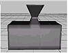
FIGURE
5.18 The spline model with its new extension
This would be an unnecessarily complex way to model the form we just
modeled. We did it to show in a very simple example the technique of detaching
splines, Cross-Sectioning, and re-attaching them to the spline cage. On
an actual model, you can use this to connect legs to a body for example,
and to extrude convoluted quad and tri areas of a spline cage in order
to add detailed features such as ears.
Using Five-Sided Patches
In MAX R3, an editable spline has a command called “Bind” that
will bind a vertex to an edge. This allows the vertex to move with the
edge whenever the edge moves. This feature can also be used to get Surface
to recognize what is essentially a five-sided patch. Beware of using this
if you plan to convert to a mesh, and especially if you need to export
the mesh to another program. When converted to meshes, five-sided patches
create strange geometry that does not translate to a .dxf
export.
|
|
|

| WARNING Five-sided
patches, formed with the Bind feature, create strange geometry when
converted to a mesh and exported.
|
Understanding the Surface Tools Method
What we’ve looked at so far gives us a fair acquaintance with the
overall concept of using Surface Tools, as well as some of the techniques
involved in the actual modeling work. In the following Surface Tools project,
the narwhale, we will use a different technique than detaching splines
and cross-sectioning to “extrude.” We will draw new lines and
connect them up to the cage by snapping vertices.
Working with Surface Tools on a more complex project involves knowing
what you are working with and applying these different techniques as appropriate.
Map out your general strategy in your head, before you even sit down to
the computer. You want to put more vertices where you need more detailed
definition. You want mostly quad patches in your result, so you want the
corresponding areas of the spline cage to be defined by four “meeting
points” of splines.
At the risk of belaboring the point, it really helps to be savvy with
the tools you will be using, because it’s impossible for a tutorial
to describe every possible situation you might come across. If you haven’t
really grokked the concept of a spline cage and its reference surface,
or if you’re unsure of why you might want snaps on or off, for example,
it’s worth reviewing the preceding sections before continuing.
Hands-on MAX: Modeling
a Narwhale with Surface Tools
Now that we’ve prepared, let’s try using Surface Tools on a
project. We’re going to model a narwhale. Let’s start with the
spline cage that will serve as our basic structure.
- 1. Reset MAX.
- 2. Create a circle in the left viewport.
- 3. In the front viewport, Shift-drag the circle
to the left and choose 6 Copies from the Clone dialog box.
- 4. In the front viewport, rotate the circles around
the Z axis, moving and scaling them to create an arrangement of circles
that looks like Figure 5.19.
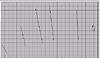
FIGURE
5.19 Arrange your cloned circles by rotating,
scaling, and moving.
|
|
|

| NOTE If you
want to start from here, you can open the file ST_narwhale_1.max
on the CD.
|
- 5. Select the rightmost circle. Just to make sure
we don’t have any world space transforms applied to the object,
click Reset XForm in the Utilities tab. Click the Reset Selected button.
This puts the transforms into an XForm modifier.
|
|
|

| TIP Reset XForm
is a vitally important utility. It’is a good habit to use it
as an ounce of prevention, especially when you’ve scaled or rotated
an object while modeling. (Scaling or rotating on a sub-object level
is fine; it’s just the transforms of the object we’re concerned
about.) It won’t make much difference while you’re modeling,
but when you animate, left-over transforms can completely screw up
your animation. Sometimes it helps to also collapse the stack after
resetting XForm. We might not need to reset XForm here; we’re
doing it in the name of establishing good habits and thinking about
animation while modeling.
|
- 6. Collapse the circle to an editable spline by
going to Modify Ø Edit Stack, and
clicking Collapse All in the dialog box. (To be on the safe side, choose
Hold/Yes when you collapse, although Yes will do.)
- 7. Click the Attach button in the Modify tab and
then click each of the other circles from right to left in order. Click
the Attach button again to turn it off. Our arrangement of circles is
now a single editable spline object with seven spline sub-objects.
- 8. Apply a CrossSection modifier (Modify Ø
More Ø CrossSection if you haven’t
customized a toolbar or Modifier set yet). You should now have a spline
cage.
Aligning the Spline Cage to Origin
Now we want to align our cage around the origin to make it easier to
cut it in half and mirror it.
- 1. Create a Point helper object anywhere.
- 2. Select the point, click the Move tool, and right-click
the Move tool to get the Transform Type-In. In world coordinates, choose
0,0,0.
- 3. Select the spline cage and click the Align tool.
Click the Select by Name button, highlight Point01, and click Pick.
In the Align dialog box, check each axis and choose Center for both
Current Object and Target Object. Our spline cage is now centered on
the origin.
- 4. Using the Select by Name tool, select the point
object, go to the Display tab, and click Hide Selected.
|
|
|
|
| NOTE An alternate
way to center the spline cage to the origin is to first center its
pivot point within the object by clicking Affect Pivot Only in the
Hierarchy tab, and then clicking Center to Object. Then turn off Affect
Pivot Only and use the Transform Type-In to move the cage to 0,0,0.
|
|
|
|
|
| TIP Assign Hide
Selected to Alt+H (Customize Ø
Preferences Ø Keyboard). You can
then hide an object with a keystroke instead of changing tabs. By
pressing 5, you can also unhide by name with a keystroke.
|
© 2000, Frol (selection,
edition, publication)
|
|
)
)
)
)