| |
| |
Mastering
3D Studio MAX R3 |
Creating
the Arm
Now the object is ready for editing at the Sub-Object level. You can
think of the existing object as the basis for the torso of our character.
(Remember what we said about demonstrating various MAX interface techniques,
so you can choose the approach that works best for you? The remaining
parts of the character will be created by a combination of edit types
found in the shortcut menus.)
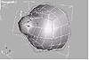
FIGURE
5.38 The half-object with MeshSmooth applied
|
|
|

| NOTE If you
want to start from here, you can open the file Organic3.max
on the CD.
|
- 1. Right-click the object and select Edit Base Object.
This brings you to the bottom of the modifier stack automatically. (You
could achieve the same results in the Modify tab by choosing Editable
Mesh from the Modifier Stack drop-down list.) Now you will create the
polygons that will enable you to create a neck, arm, and leg.
- 2. From the shortcut menu, select Sub-Object Ø
Edge.
- 3. In the front viewport, and while still at the
Edge level, click the second shoulder edge (see Figure 5.39).
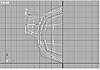
FIGURE
5.39 This edge (the white line with a gizmo)
will be our character’s shoulder.
- 4. In the perspective viewport, right-click the
selected edge to bring up the shortcut menu. Select Chamfer / Bevel
Ø Chamfer Edge.
- 5. In the perspective viewport, slowly move your
mouse pointer over the selected edge. The cursor changes to the Edge
Chamfer tool.
- 6. Slowly click and drag your mouse to create a
new face by “splitting” or chamfering the selected edge.
|
|
|
|
| NOTE If you
“over-chamfer” during this operation, use the Undo to return
to a state where you have only one edge selected, and repeat the Chamfer
Edge command slowly. You should notice that not only did you create
a central polygon for the arm to be extracted from, but the surrounding
polygons, vertices, and edges have also changed to accommodate the
new geometry you created. Also note that the effects of the MeshSmooth
modifier are updating in all the viewports.
|
You should now have a chamfered edge and something like Figure 5.40.
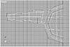
FIGURE
5.40 The right shoulder in sub-object mode
- 7. From the shortcut menu, select Sub-Object Ø
Polygon.
- 8. Select the newly created arm socket.
- 9. With the polygon selected, choose Extrude Ø
Polygon from the shortcut menu.
- 10. In the perspective viewport, slowly move your
mouse pointer over the selected polygon. Notice the pointer changing
to the Extrude tool.
- 11. Slowly click and drag your mouse to create a
new face by extruding the selected polygon.
Again, combinations of some pretty spectacular things are happening in
the viewports. First, polygons, vertices, and edges are being created.
The MeshSmooth is updating the underlying, low-resolution model, and the
newly created (end) polygon is now the current selection.
- 12. Immediately lock this Sub-Object polygon selection
by hitting the spacebar. You should now have something that looks like
Figure 5.41.
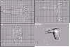
FIGURE
5.41 Extruded polygons
- 13. From the shortcut menu, select Rotate.
- 14. In the front viewport, rotate the selected polygon
around the Z axis, which is blue. Bring the polygon to the vertical
position.
- 15. Select Move from the shortcut menu.
- 16. In the front viewport, move the selection down
in the Y axis. Figure 5.42 shows our model at this stage.
FIGURE
5.42 Front view of the soon-to-be arm
- 17. Unlock the selection by hitting the spacebar,
but keep the selection active.
- 18. From the shortcut menu, select Chamfer/Bevel
Ø Bevel Polygon.
- 19. In the Perspective viewport, slowly move your
mouse pointer over the selected polygon. The pointer changes to the
Bevel Polygon tool.
|
|
|

| WARNING This
next step of beveling has two parts that happen in one menu operation.
That is, the first part of the operation will require one mouse click,
and to finish the operation will require a second mouse click.
|
- 20. First, slowly click and drag your mouse to create
something similar to the previous arm extrusion. When you finish and
let up the mouse button, immediately click again to define the amount
of beveling to be performed.
- 21. From the shortcut menu, repeat Chamfer/Bevel
Ø Bevel Polygon on the currently
selected polygon. Your torso should now look something like Figure 5.43.
FIGURE
5.43 Extruding an arm
Before we create the hand, let’s move vertices around (one at a
time or in groups) to pull the MeshSmooth(ed) torso object into a bit
more recognizable shape.
- 22. From the shortcut menu, choose Sub-Object Ø
Vertex.
- 23. In the front and top viewports, use the Move
tool to move vertices into a shape resembling Figure 5.44. You may have
to use Zoom Extents All as you change the overall shape of the torso.
- 24. Save or hold your work.
FIGURE
5.44 Extending the torso
|
|
|
|
| NOTE To ensure
you are selecting “through” the model to the corresponding
“back” vertices (relative to each viewport) at the same
time, be certain to marquee-select vertices rather than clicking each
vertex. Also, make sure you use the constraining axis to move these
selections, especially when affecting vertices along the side that
will become the centerline of the object as seen from the front.
|
Giving the
Character a Hand
Now let’s return to the arm we extruded, to add a right hand.
|
|
|
|
| NOTE If you
want to begin from this point, load Organic04.max from
the CD-ROM.
|
- 1. In the Perspective viewport, zoom into the area
where the hand will be created.
- 2. From the shortcut menu, chose Cut Ø
Edge.
|
|
|
|
| WARNING This
next step of cutting an edge has two parts that happen in one menu
operation...
|
- 3. Zoom in and move your cursor over the front edge
of the end polygon of the arm. It will change from an arrow to a crosshair
when you are over the edge. Halfway down the edge, click once to start
the Cut operation. Then drag a dotted line to the center of the back
edge and click a second time.
- 4. Right-click once to exit the Cut operation. The
newly created edge will become selected, and will be indicated by a
yellow selection color.
- 5. Using the shortcut menu to change to Sub-Object
Ø Polygon level and select the top
half of the newly edited end of the arm. Figure 5.45 shows what your
selection should look like.
FIGURE
5.45 Selecting part of the end of the arm
- 6. From the shortcut menu, choose Extrude Ø
Polygon.
- 7. Perform two successive extrusions outward to
form the basis of the hand. The first sweeps out to the base of the
fingers, and the second forms the fingers themselves. The polygon created
at the front of the hand by these two extrusions will become the socket
for the thumb to be extracted.
- 8. Extrude the base of the thumb forward from the
hand, and lock the selection (thumb end polygon) by pressing the spacebar.
- 9. Change to the Rotate tool with the shortcut menus,
and in the top viewport, slightly rotate the selected polygon on the
Z axis.
- 10. Finish off the creation of the thumb by performing
a Chamfer/Bevel Ø Bevel Polygon.
- 11. Unlock the selection by hitting the spacebar
a second time and switch to Sub-Object ØVertex
level.
- 12. Use the Move tool to arrange the various hand
vertices, ending up with something resembling Figure 5.46.
FIGURE
5.46 The hand is taking shape.
As with the narwhale earlier in this chapter, we’re not modeling
all the detail that’s possible here. You can take these techniques
onward to create individual fingers.
© 2000, Frol (selection,
edition, publication)
|
|
)
)
)
)
)
)
)
)
)
)
)
)
)
)
)
)
)
)