| |
| |
Mastering
3D Studio MAX R3 |
Making the Object Whole
You should now have a completed half of the simple character. We’ll
mirror this model and once again go through the technique for zipping
the two halves together. This is a good time to check that you’ve
modeled all the symmetrical elements you will want. Once you’ve created
and joined the other half of the model, it will be more difficult to make
changes to both sides that stay consistent with each other.
|
|
|

| NOTE If you
want to work from this point, load Organic07.max from
the CD-ROM.
|
- 1. With the entire model selected, chose Jump to
Top of Stack from the short-cut menu.
- 2. From the Edit menu, pick Clone. The Clone floater
will appear.
- 3. Use Copy (the default) as the clone method for
the new object and click OK to exit the floater. An exact copy of the
half of the model exists and is selected, in the same exact location
in the scene as the original.
- 4. Choose Tools Ø
Mirror. The Mirror floater will appear. The default Mirror Axis of X
coincidentally happens to be the desired mirror in this case. You will
notice that the clone is now a left half to the character model, and
it is (still) selected.
- 5. Click OK to commit the change and exit the Mirror
floater.
- 6. Lock the selection by hitting the spacebar.
- 7. With the new half still selected bring up the
shortcut menu and choose Edit Stack. Select Collapse All. This will
collapse the modifier stack for this object only. You will notice in
the stack that the MeshSmooth is gone, but the results are present in
the resulting editable mesh.
- 8. Bring up the shortcut menu and go to Attach /
Detach Ø Attach.
- 9. Click the right half of the model to attach it
to the current selection (the left half).
- 10. Unlock the selection and right-click off the
model in any viewport to exit the Attach mode.
- 11. Do a quick render of the perspective viewport.
You should now see the completed model, but notice a slight seam in
the smoothing along the centerline. This is because the model, while
it appears whole, is not. The centerline vertices of the previous two
halves are, indeed, coincident to their mirrored self, but they need
to be welded to complete the model.
- 12. Right-click the front viewport to select it.
Click the Min/Max icon from the Navigation controls to make this viewport
full screen.
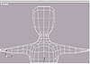
- 13. Zoom into the upper section of the model as
seen in Figure 5.52.
- 14. From the shortcut menu, go to the Sub-Object
Ø Vertex level.
- 15. Marquee-select the vertices down the centerline
of the model. They will turn red when selected.
FIGURE
5.52 Front view, upper torso
|
|
|

| WARNING Make
sure you use Select Object with the Rectangular Selection Region tool.
This will verify you are only selecting and not accidentally modifying
the vertices, and will also select “through” the model so
the backside centerline vertices are also selected. Don’t select
any vertices not on the centerline.
|
- 16. Use the Pan tool from the Viewport Navigation
controls to pan the front viewport down to the mid-section of the body,
then right-click the viewport to deactivate the Pan tool.
|
|
|
|
| NOTE If you
hold down the Ctrl key, you should see a small “+” sign
appear next to your cursor, indicating you will be adding to the current
selection of vertices. If you hold down the Alt key, you get a small
“–” sign, indicating you will be subtracting. Use the
Alt key to deselect any non-centerline vertices you mistakenly selected.
|
- 17. Select the remaining centerline vertices using
the Rectangular Selection Region tool.
When you have all the centerline vertices selected, scroll the Modify
tab so you can see both the Selection rollout and the Weld section of
the Edit Geometry rollout, as in Figure 5.53. (You may have to close the
Soft Selection rollout to see both sections.) In the Selection area, you
can see that MAX is showing how many vertices are selected; make a mental
note of this number.
- 18. In the Weld section, click the Selected button
to weld all the coincident vertices. The selection quantity should be
cut exactly in half if the weld was performed correctly.
|
|
|
|
| NOTE If the
number of vertices does not equal half the previously selected count,
you may have to undo the previous weld and adjust the weld threshold
spinner.
|
FIGURE
5.53 The Command Panel just before Welding the
halves together
Re-render the perspective viewport, and you will see the completed character
model (Figure 5.54) without any noticeable seam down the centerline.
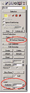
FIGURE
5.54 Our character is complete.
As you can imagine, this technique can be used for many things beyond
characters and symmetrical models. The obvious advantage is that you can
work on a relatively low-polygon version of the model and maintain a higher
level of control than if you were to model the smoothed object itself.
Also, this technique does not need to exclusively be applied to organic
models. In nature, there are no true straight lines or perfect corners,
so you can alternate the MeshSmooth parameters and get rounded architecture
or automobiles, for example.
Summary
In this chapter, we looked at the various types of splines that are the
basis of patch and NURBS models. We discussed the nature of Bezier patches
and the different ways of modeling objects in them. You learned the tremendously
powerful method of creating patch models with MAX Surface Tools and used
this to create an organic model. We explored NURBS modeling and the array
of tools available for creating NURBS models in MAX. Finally, we discussed
the subdivision surface modeling method for creating mesh models, examined
the NURMS option of the MeshSmooth modifier (a tool unique to MAX), and
built a new model using this method.
In the next chapter, you will be introduced to basic animation principles
and to the animation tools in MAX. You’ll learn simple animation
methods and will apply these to different kinds of objects to create diverse
animations. You’re also ready to spend some time “under the
hood” of MAX, looking at animation controllers.
© 2000, Frol (selection,
edition, publication)
|
|
)
)
)
)
)
)