| |
| |
Mastering
3D Studio MAX R3 |
Double Sided materials have just three parameters settings: Facing Material
for the front material, Back Material for the back, and Translucency to
determine the amount that the materials blend (from zero to 100 percent).
Let’s create a double-sided material:
- 1. In the Material Editor, create a Double Sided
material by clicking the Type button and selecting Double Sided from
the list of materials.
- 2. Click the Facing Material button.
- 3. Create a material of any type that you want to
assign to the front faces.
- 4. Click Go to Parent or use the Material/Map Browser
to return to the top level of the material.
- 5. Click the Back Material button and create a material
for the back faces.
- 6. Assign the material to an open object, such as
a plane, a bowl, or a teapot without a lid.
- 7. Render the scene.
Creating
a Top/Bottom Material
Top/Bottom materials assign one material to all the faces whose normals
point upward, and the other material to the rest of the faces whose normals
point downward (the settings used to create Top/Bottom materials are defined
in Table 9.6). In the demonstration in Figure 9.14, the top material uses
a foliage map and the bottom map uses a stone map. (We mirrored and tiled
the maps to make the final patterns.) At the boundary between up- and
down-facing normals, you can blend the materials. You can also move the
boundary up and down along the object’s Z axis. When you change the
material from local to world coordinates, MAX determines the orientation
of surface normals relative to the Z axis of the world coordinate system
of the scene rather than the coordinate system of the object. The world-orientation
of the material will then persist when the object is rotated.
Table 9.6: TOP/BOTTOM BASIC PARAMETERS
| Top Material
| Specifies the material assignment for
faces that point upward toward the top of the object
|
| Bottom Material
| Specifies the material assignment for
faces that point downward toward the bottom of the object
|
| World Coordinates
| Uses the world system of reference for
determining up/down orientation of faces
|
| Local Coordinates
| Uses the object’s local system of
reference for determining up/down orientation of faces
|
| Blend
| Determines the amount of blending between
materials
|
| Position
| Specifies the position of the blending
boundary
|
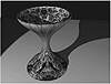
FIGURE
9.14 A vase mapped with a Top/Bottom material
Let’s create a Top/Bottom material:
- 1. In the Material Editor, create a Top/Bottom material
by clicking the Type button and selecting Top/Bottom from the list of
materials.
- 2. Click the Top Material button.
- 3. Create a material of any type that you want to
assign to the top faces.
- 4. Click Go to Parent or use the Material/Map Browser
to return to the top level of the material.
- 5. Click the Bottom Material button and create a
material for the bottom faces.
- 6. Position the boundary between the two materials.
- 7. Set the amount that you want the two materials
to blend at the boundary.
- 8. Choose Local Coordinates if you want to keep
the material aligned to the object’s Z axis.
- 9. Assign the material to curved surface with faces
that point both up and down.
- 10. Render the scene.
Creating
a Composite Material
Composite materials allow you to superimpose up to nine different materials
in succession on top of a base material. The final outcome depends on
the color and opacity of the component materials, the order in which they
are laid down, and the method of compositing (see Figure 9.15). Figure
9.16 shows an example of an object given a Composite material. The base
material contains a Cellular map. The first composite material contains
a Checker map and the second uses Earth2.jpg, which is
found in the Maps\space folder.
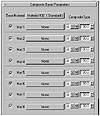
FIGURE
9.15 The Composite Basic Parameters rollout.
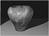
Figure
9.16 A vase mapped with a Composite material
made up of three different materials
Under Composite Type, there are three options for compositing each material.
The A button adds the color of the new material to what has been
laid down previously, excluding areas of transparency. The S button subtracts
the color of the new material from what is already present, excluding
areas of transparency. For both the Additive and Subtractive options,
values can range from zero to 200 percent. Above 100 percent the material
becomes “overloaded” so that transparent areas of the material
become opaque.
The M (mix) option blends the color and opacity of the current
material with the previous state, just like the Blend material. Values
range from zero to 100 percent. At zero, there is no blending and the
current material has no effect. When Mix is set to 50 percent, they blend
evenly. At 100 percent mixing, the color and opacity of the current material
completely override the composite below it. (Note that the highest-numbered
material is at the top of the composite pile, despite the rollout order.)
Each piece of the Basic Parameters rollout is explained in Table 9.7.
Table 9.7: COMPOSITE BASIC PARAMETERS
| Parameter
| Function
|
| Base Material
| The base color (bottom layer) of the composite
material
|
| Mat. 1 through 9
| Materials that add, subtract, and mix
with the base
|
| A button
| Adds the current material’s color
to the composite
|
| S button
| Subtracts the current material’s
color to the composite
|
| M button
| Blends the current material’s color
and opacity with the composite material
|
| Amount spinner
| Sets the amount that the material affects
the composite beneath
|
|
|
|

| TIP For complicated
materials like the Composite material, it helps to have a bigger view.
Double-clicking the material slot in the Material Editor magnifies
the display.
|
Let’s create a composite material:
- 1. In the Material Editor, create a Composite material
by clicking the Type button and selecting Composite from the list of
materials.
- 2. Click the Base Material button.
- 3. Create a material of any type for the base level
material.
- 4. Click Go to Parent or use the Material/Map Browser
to return to the top level of the material.
- 5. Create the first material that you want to composite
with the base.
- 6. Return to the top level.
- 7. To the right of the first material, choose A
for additive, S for subtractive, or M for mix. Remember that transparent
areas won’t affect the base color unless you mix the material.
- 8. Set the composite amount by dragging the spinner.
- 9. Repeat steps 5 through 8 for as many new materials
as you want to composite, to a maximum of nine.
- 10. Assign the material to an object.
- 11. Render the scene.
© 2000, Frol (selection,
edition, publication)
|
|
)
)
)
)
)
)