| |
| |
Mastering
3D Studio MAX R3 |
Creating
the Loft Object Cross-Section
Let’s create the shape to be lofted along the path.
- 1. Go to Create Ø
Shapes and click the Circle button.
- 2. Drag out a small circle in the lower-right corner
of your left viewport.
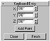
FIGURE
11.19 Filleted vertices on our faucet spline
- 3. Enter a Radius of 0.5" in the Parameters rollout
of the Create tab.
- 4. Rename Circle01 to shape_faucet.
- 5. Save your file as faucet_2.max.
|
|
|

| NOTE If you
want to start from here, you can load faucet_2.max
from the CD.
|
Lofting the
Faucet
Now let’s make the faucet.
- 1. In the left viewport, select the path_faucet
spline.
- 2. In the Create tab, select the Geometry category
and choose Compound Objects from the drop-down list. Click the Loft
button, make sure Instance is checked, and then click the Get Shape
button. Click the circle shape in the viewport. The shape lofts along
the path; it’s looking more like a faucet now, as shown in Figure
11.20.
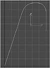
FIGURE
11.20 We’ve Lofted the faucet.
- 3. Go to the Modify tab and rename Loft01 to faucet_loft.
- 4. Right-click the faucet and select Properties
from the shortcut menu. In the Object Properties dialog box, you should
find that the face count on the faucet is 1484.
Using Faces
Efficiently
Creating efficient models is important. The more polygons in your scene,
the longer it takes to render and the more it will bog down your system.
Let’s reduce the number of faces in the loft.
- 1. Click OK to close the Object Properties dialog
box. Open the Skin Parameters rollout in the Modify tab and change the
Shape Steps to 3 and the Path Steps to 2. The Faucet loft becomes a
little less faceted.
- 2. Right-click in the viewport again to view the
face count in the Properties dialog box. Reducing these steps brought
the faces down to about 1/3 of the original count. Close the dialog
box.
Because we will be animating a bulge of water moving through the faucet,
the loft will need more faces than usual to avoid looking faceted during
the animation. Instead of increasing our path steps in the Skin Parameters,
we can refine the path by adding vertices where we need more detail, creating
more faces in the loft there.
- 3. Press H to bring up the Select by Name dialog
box. Notice that there is also a Line01, an instance of the loft shape
created when we made the loft. Choose path_faucet in the list and select
it.
- 4. Right-click the left viewport and press W to
maximize the viewport. Go to the Vertex sub-object level of the path_faucet
spline.
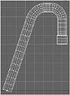
- 5. Click the Refine button in the Modify tab. Click
the path_faucet object to add vertices as shown in Figure 11.21. Add
a vertex bisecting the first long segment, then bisect each half again,
adding two vertices between the first arc of the faucet and one in the
second arc. Then divide the segment at the spout end in half. Two steps
appear on the loft between each vertex on the path, because we chose
a Path Steps value of 2.
- 6. Select the faucet, right-click to check the face
count in the Object Properties dialog box, then close it. Your loft
should have 1276 faces. The faces add up quickly, don’t they? We
did manage to save ourselves more than 200 faces, and more importantly
we have faces where we need them. Save your file as faucet_3.max.
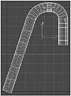
FIGURE
11.21 These are the vertices to be added.
Scaling to Make a Spout
Let’s add the spout at the end of the faucet by using some loft
deformations.
- 1. Load faucet3.max or continue working
with your scene.
- 2. Select the faucet_loft object and go to the Deformations
rollout on the Modify tab. Open it and click the Scale button to bring
up the Scale Deformation window. You may recall using this in Chapter
5. We are going to add control points that define the corners of the
spout at the end of the faucet. If you need to refer to the original
sketch, go to File Ø View File and
select faucet_template.tif.
|
|
|

| 3. Click the Insert
Corner Point button in the Scale Deformation dialog box. Place a control
point at the far right end of the line, then add two more control
points to the left of this point, as shown in Figure 11.22.
|
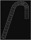
FIGURE
11.22 Add three scale deformation points (the
squares on the horizontal line).

| 4. Using the Move Control
Point tool, select the second control point from the right. Enter
the values of 99.5 (representing the horizontal position of the control
point) and 115 (representing the vertical position of the control
point) in the numeric fields along the bottom of the Scale Deformation
window. Select the next control point to the left and enter the values
of 94 horizontal and 115 vertical. Select the last control point you
added and enter the values of 93.5 and 100. Your faucet loft object
should look like Figure 11.23. Save your file as faucet_4.max.
|
- 5. Close the Scale Deformation window. Your faucet
is complete.
Adding a
Space Warp with a Path Controller
Now we need to work on making the faucet bulge with the burst of water.
We will use a Displace space warp to create the effect. First we need
to create a path for the space warp to follow through the faucet. We can
use the path_faucet spline to do that.
- 1. Open faucet_4.max or continue
working with your current scene.
FIGURE
11.23 Deforming the loft creates this spout.
- 2. Using the Select By Name tool (H key), select
path_faucet. Choose Clone in the Edit menu. In the dialog box, name
the clone path_displace and check Copy. Click OK to close the dialog
box.
- 3. In the Create tab, choose the Space Warps category
and click the Displace button. Change the Map type from Planar to Spherical.
Drag out a Displace space warp gizmo in the viewport until it is just
a bit larger than the shape_faucet object, about 5/8", and let go of
the mouse button.

| 4. In the Motion tab, open the Assign
Controller rollout. Select the Position track and click the Assign Controller
button. Select Path and click OK to close the dialog box. Click the
Pick Path button and press H to bring up the Select By Name dialog box.
Select path_displace and click Pick to close the dialog box. The Displace
gizmo jumps to the beginning of the path.
|
- 5. Play the animation to see that the gizmo follows
the path. Notice that the animation slows down where there are more
vertices and speeds up where there are fewer. If you wanted a consistent
speed, you would check Constant Velocity in the Path Parameters rollout
of the Motion tab.
- 6. Check Follow in the Motion tab. Play the animation
again to see how the gizmo’s rotation now also follows the path.
Editing the
Space Warp Timing
Now we will take out some of the vertices of our path to speed up the
motion around the curves just a bit. We’ll add a vertex at the center
of the arcs, then delete all other vertices to refine the spline. Some
distortion will happen to the curves. We will use the path_faucet object
as a template to adjust the arcs back to their original shape.
- 1. Using the Select by Name tool, select path_displace,
path_faucet and Displace01. In the Display tab, click the Hide Unselected
button. The objects you selected should now be the only ones in your
viewport.
- 2. Using Select By Name, select the path_displace
object. In the Modify tab, click the Vertex Sub-Object button. Using
the Region Zoom tool, zoom in close to the two curves at the top of
the path. You want to be able to see all of the vertices that make up
the two curves.
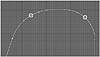
- 3. Click the Refine button in the Modify tab. Click
the middle of the center segment of both arcs to add two vertices, as
circled in Figure 11.24. Click the Refine button again to turn it off.
FIGURE
11.24 After we refine the curve with these
new vertices, we’ll delete four old ones.
- 4. Using Ctrl to add to your selection and Alt to
subtract, select the four vertices on either side of the new vertices.
Press the Delete key. We’ve lost some of the smooth curvature,
but we can still see path_faucet as a reference.
- 5. Select one of the center vertices that you added.
Drag the Bezier handles out until the curve matches the path_faucet
spline behind it. Then do the same thing with the handles of the other
vertex you added.
- 6. Now we will do the same thing with the short
horizontal segment at the top of the path. Refine the segment by adding
a vertex in the center. Delete the vertices to either side of the new
vertex, as shown in Figure 11.25, and then adjust the Bezier handles
of the new vertex so the curvature matches the underlying template.
FIGURE
11.25 Delete these vertices and then restore
the curvature with Bezier handles

| 7. Turn off the Sub-Object
button and click Zoom Extents Selected. Play the animation again.
Notice that the Displace gizmo moves through the curves a little more
quickly and smoothly, yet is slow enough to give the illusion of having
to work a little harder to get through the curves. Save your file
as faucet_5.max.
|
© 2000, Frol (selection,
edition, publication)
|
|
)
)
)
)
)
)
)
)
)
)
)
)
)
)