| |
| |
Mastering
3D Studio MAX R3 |
Other Maps
The last types of maps that can define a material are labeled Other in
the Material/ Map Browser. These types (listed in Table 8.10) are made
up of a series of maps that help generate reflections and refraction and
are almost always used in the material’s Reflection and Refraction
channels (see Chapter 9 for more information on reflection and refraction).
Table 8.10: Types of Reflection Maps
| Type
| Use
|
| Flat Mirror
| Creates reflections for flat surfaces
(typically assigned to faces, not objects)
|
| Raytrace
| Provides both a very accurate reflection
and refraction
|
| Reflect/Refract
| Simulates Reflection and Refraction based
on the surrounding information for the scanline renderer (not as accurate
as Raytrace)
|
| Thin Wall Refraction
| Simulates the effect of looking through
water or a plate glass
|
Now that we have gone over all the map types, we are going to create
some of our own materials using these and some of the other tools covered
earlier. This exercise will provide you with an overall look at some of
the information in this chapter. The settings in this exercise are only
guidelines; feel free to experiment with your own ideas and settings.
The best way to find out how maps react to different channels of a material
is to try new things out with them. Be creative with it and have some
fun. You might be surprised what you come up with.
Open the file named map.max from the Chapter 8 folder
on the CD-ROM that accompanies this book. The file contains a small scene
that has been setup with a camera and a light source. What we are going
to do is create some realistic-looking materials for the ceiling, floor,
walls, and objects on the floor.
- 1. Start off by rendering the scene, so you have
something to compare to as we move forward.
- 2. Let’s work on the walls first. Select the
walls.
- 3. Open the Material Editor and assign Material
#1 to the walls.
- 4. Change the Diffuse color so its RGB values are
250,211,91.
- 5. Change the Ambient color to 144,121,53.
- 6. Set the Specular color to pure white: 255,255,255.
- 7. Render the scene again.
The walls look good but maybe too perfect. Let’s try and make them
look a bit more realistic by giving them some scattered patches of dirt
or color—something to break it up. To do that, let’s place a
Smoke map in the Specular channel of the material.
- 1. In the Maps rollout next to Specular Color, click
the None button and choose Smoke from the 3D maps list.
- 2. To see the Smoke effect in the specular color
of the material, you must adjust the Specular Level and some of the
Smoke Map Parameters. In the Maps rollout, change the value for the
Specular Level setting to 84.
- 3. Go to the Smoke Map rollout and change color
#2 to 13,117,247.
- 4. Next, change the Size value to 100.
- 5. Render the scene (see Figure 8.27).
The walls now look a bit less stale. Let’s move on the floor area.
- 1. Select the floor and apply Material #2 to it.
- 2. Place a Checker map in the Diffuse Color channel.
- 3. Render the scene.
- 4. The Checker map is too large for the floor, so
let’s change that. Go to the Diffuse Color level, to the Checker
rollout, and change the Tiling from 1 to 7 in both the U and the V.
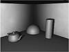
FIGURE
8.27 Dirty walls
- 5. Render the scene again. That looks much better.
- 6. Now let’s give the floor a bit of reflection.
Put a Flat Mirror map in the Reflection slot.
- 7. Render your scene. Looks good, but there’s
too much reflection on the floor.
- 8. Set the value of the reflection to 30.
- 9. Render again and look at the difference (see
Figure 8.28).
Now let’s finish it off with some materials on the objects. Let’s
do the teapot first.
- 1. Apply Material #3 to the teapot.
- 2. Make a Chrome material for the teapot.
- 3. In the Reflection channel, place a Raytrace map
(not a material).
- 4. Render your scene.
- 5. Change the Ambient and the Diffuse colors to
pure black. The Specular color should be pure white.
- 6. Set Specular Level to 60.
- 7. Set Glossiness to 70.
- 8. Render the scene again (see Figure 8.29).
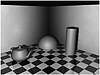
FIGURE
8.28 The floor with Checker and Flat Mirror
maps
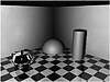
FIGURE
8.29 A Chrome teapot Let’s do the sphere
next.
- 1. Apply Material #4 to the scene.
- 2. Place a Planet map in the Diffuse Color channel.
- 3. In the Diffuse Color channel, change Continent
Size to 25.
- 4. Render the scene.
- 5. In the Bump channel, place a Cellular map.
- 6. In the Bump channel, go to Cell Characteristics.
Change its value to Chips and change Size to 6.9.
- 7. Make sure the value in the Bump slot is 70.
- 8. Render your scene again (see Figure 8.30).
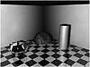
FIGURE
8.30 This scene is almost done.
The cylinder is the only thing left.
- 1. Apply Material #4 to the cylinder.
- 2. Change the material to the Anisotropic shader.
- 3. Set the Diffuse color to a light blue (like 3,144,253)
and Ambient to a darker blue (say, 1,34,60). The Specular color should
be pure white.
- 4. Set these values: Opacity 10, Diffuse Level 138,
Specular Level 125, Glossiness 40, Anisotropy 75.
- 5. Render the final scene (see Figure 8.31).
FIGURE
8.31 Ta da! The final scene
Summary
As you can see, even the basics for this part of the program can be a
challenging but immersive experience. After this chapter, you should be
familiar with key elements of the Materials Editor and some of its functions
and features, including the difference between a material and a map, different
map types, and various shaders and their uses. Finally, we finished with
exercises that, hopefully, brought it all together for you.
In the next chapter, we will concentrate on more sophisticated materials.
This advanced material discussion will cover the creation and uses of
complex materials such as Raytrace, Matte/Shadow, and Compound materials.
© 2000, Frol (selection,
edition, publication)
|
|
)
)
)
)
)
)
)
)
)
)