| |
| |
Mastering
3D Studio MAX R3 |
These steps first select the front face of the current object, then apply
a material ID to this polygon, and finally give it mapping coordinates.
This method uses a mindset similar to the Mesh Select and DeleteMesh combination
that was previously described in this exercise. The MeshSelect modifiers
pass a selection upward, on which the following modifiers can each do
their thing—in this case, apply a Material ID and UVW Map coordinates.
Again, this is non-destructive, parametric modeling.
Using the technique described under “Renaming the Stack” above,
change the names of these three modifiers. We’ve suggested some names
for you in Figure 4.24.
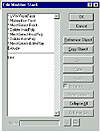
FIGURE
4.24 A renamed modifier stack
This renaming may seem tedious for this exercise, but it is invaluable
if you are working with a team of artists who will be accessing a modifier
stack. Since polygons and groups of polygons will be individually named
and given mapping coordinates, it is important to be able to know where
to jump to in the stack, should you later want to edit some parameter
nested therein.
- 6. In the modifier stack, go to the Material on
Front modifier.
- 7. Using the Material ID spinners, try a few different
values in the viewport.
You will notice the ID value changing and the corresponding bitmap being
displayed on the front polygon of the house in the shaded, perspective
viewport. When you’re finished, return the Material ID to 1.
- 8. In the Modifier Stack, go “up” to the
UVW-FrontFace modifier.
In the Parameters rollout, under the Mapping choices, try cycling through
the choices of Planar, Cylindrical, Spherical, and so on. Notice the often-strange
results in the shaded viewport. When you’re finished, return to Planar
mapping.
- 9. In the Alignment rollout of the UVW modifier,
click the Fit button. The front of the house should now be properly
mapped.
|
|
|

| NOTE If the front of the
house does not, at this point, resemble Figure 4.23, continue this
exercise after loading the file House03.max from the
CD.
|
The mapping for the front of the house is complete. Next, we will apply
these same techniques to the sides of the front room. From this point
on, it will be assumed that you will rename a modifier in the Edit Stack
dialog box after it has been applied. So that you may select both side
polys of the front part of the house at the same time, you will now adjust
the viewports so that you have a left and a right view of the house.
- 10. Change the left viewport to a perspective or
user viewport and view from slightly above the house, using the Arc
Rotate tool.
- 11. With the HouseShape01 object selected and Polygon
sub-object level chosen, apply another MeshSelect modifier.
- 12. While holding down the Ctrl key, click the two
opposite sides of the front section of this house. You may want to switch
to wireframe view to see the results a bit more clearly. The two polygons
should be selected, and you should have something similar to Figure
4.25.
- 13. Apply a Material modifier and give the selection
an ID of 2.
- 14. Apply a UVW Mapping modifier of Planar type
with X Alignment. You will notice the window maps placed on the front
of the house, but since the polygons from this section of the house
go “into” the model, the map is getting stretched long. This
can be fixed by adjusting the scale of the UVW modifier mapping gizmo.
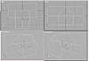
FIGURE
4.25 Opposite sides of the house are selected.
- 15. Enter the Sub-Object level of the UVW Mapping
modifier. and lock the selection using the spacebar.
- 16. Pick the Fit button under the UVW Alignment.
- 17. From the Scale icon fly-out, choose the second
tool (named Select and Non-Uniform Scale). This lets you scale the mapping
coordinates along one axis.
- 18. In the perspective viewport, scale the mapping
gizmo only along the Y axis by selecting the green-arrow Y axis handle
at the start of the scaling process.
|
|
|
|
| NOTE During this operation,
you will notice the map scales along one axis; the value of the delta
(or change) in the scale updates at the bottom of the MAX interface.
|
- 19. Make sure to scale along only the Y axis, and
scale to 60 percent.
- 20. Switch to the Move tool.
- 21. Using the same green-arrow handle in the perspective
viewport, move the gizmo along the Y axis until the window is centered
on the side of the house and there are no “partial windows”
viewable on the side. The arrow in Figure 4.26 indicates the centered
window.
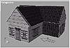
FIGURE
4.26 The side windows are centered.
- 22. Unlock the selection using the spacebar.
- 23. Rename the last three modifiers according to
the modifier stack for the object HouseShape01 in Figure 4.27. Save
or hold your file.
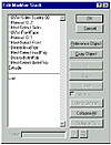
FIGURE
4.27 The modifier stack after mapping the
windows
© 2000, Frol (selection,
edition, publication)
|
|
)
)
)
)
)
)
)
)